11.07
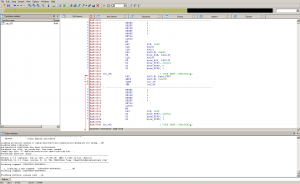
Earlier this week I started to work on reverse engineering code running on the Gamecube DSP, which is as far as I know a custom made CPU optimized for sound processing (mixing several sounds, decoding compressed sample formats, that kind of stuff). The Dolphin emulator has an implementation of a JIT and an interpreter for this CPU, as well as a basic disassembler and assembler used for debugging. But reverse engineering a program made of 4000 instructions using a basic disassembler which outputs a text file is really… primitive compared to the features provided by modern tools like IDA. I’ve wanted to learn more about how to write IDA plugins for a long time, so I started to work on a processor module to handle the GC/Wii DSP in IDA. I’m going to talk about how an IDA processor module is written, and some thoughts I had when writing this module (warning: rant incoming).
First of all, the complete code of this module can be found on my Bitbucket account. It is written for IDA 6.1 with IDAPython and Python 2.7. For those who don’t know about it, IDAPython is a plugin for IDA which allows IDA scripting in Python using (almost) the same API as normal C modules. Some modules distributed with IDA 6.1 are programmed like that: for example, spu.py (for Sony’s PS3 SPU cores) and msp430.py (for TI MSP430 CPU) so it’s easy to go look at the code in these modules if you have a problem.
A Python processor module needs to export a function called PROCESSOR_ENTRY, which returns an instance of a subclass of idaapi.processor_t, the base class of processor module objects. The object needs to define some properties, for example a bitfield of features needed or supported by the plugin, the CPU name, all of the CPU instructions and registers, as well as the number of bits in a byte and all kind of properties like that. Four functions must also be supported:
- ana, which stands for analyze, reads bytes at a given address and decodes them to get an instruction. The method needs to fill the cmd_t object named self.cmd and return the number of bytes read.
- out and outop handle outputting respectively an instruction and an instruction operand. They are called after ana, with self.cmd initialized to what you set it before.
- emu emulates the behavior of an instruction to create cross-references and code flow edges. For example, a RET instruction needs to stop the current basic block, and a CALL instruction will have a reference to another function.
That’s all you need to implement for an IDA processor module. Obviously it is not that easy, you still need to decode the ISA of your CPU and handle operands correctly, etc. There is not a lot more to tell about this so let’s talk about what I think of the IDA API now that I manipulated it a bit.
It’s crap. It kind of works, but has almost no documentation, really few examples and even the documentation can be quite misleading when you start using non conventional features. For example, to specify that your CPU manipulates big endian data, you need to guess that you have to implement notify_init and set cvar.inf.mf to True. By the way, mf means MSB First… calling the field be or big_endian would probably make too much sense. But wait, even setting mf to True is not always enough! When your CPU uses bytes with more than 8 bits (the GC DSP uses 16 bits in a byte), you also need to set cvar.inf.wide_high_byte_first to True. Note that for two fields that do almost the same thing, the two names are completely different.
Talking about names:
- ua_add_cref
- out_tagon
- OutLong
These three functions are all from the IDA API. Not inconsistent enough? Let’s look at the constant names: o_void, fl_F, CF_CALL. I don’t think I have to rant more about this, it’s simply stupid and you always have to look up in the C++ header files (not the documentation, it doesn’t exist) to check how a function is written.
Some things in the IDA API clearly have been written for the x86 CPU and can’t be easily generalized for other CPUs. For example, each CPU module need to define a code segment register and a data segment register, even when segmentation makes no sense at all. I looked at the SPU and the MSP430 plugins and both of those define fake registers just to please IDA and to make it think that there is a data and code segment. Another problem like that is when your CPU has bytes with more than 8 bits. The API is completely inconsistant about when a byte means 8 bits or when a byte means the native byte of your CPU. For example, the get_full_byte function reads a native byte from your CPU, but the ua_next_byte returns an 8 bit byte. Both use the same terminology and you can’t guess what is the right one to use without trying.
I also encountered some very strange bugs when coding this plugin. For example, each cmd_t object you initialize with your ana function has a specval field you can use to store custom values in it for the emu and out functions, but it was always set to 0 in ana and emu even after setting some bits in it.
Conclusion on this experience: the IDA processor module API works quite well but has evolved without any real design decisions, leading to a big clusterfuck of randomly named functions and words that don’t mean the same thing in all occasions. I spent more time fighting with the API than coding the disassembler, and I think this is quite a problem.
